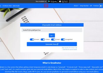
Gmailnator Top 6 Most Important Things You Need To Know
Do you know over 100 billion spam emails are sent daily? It's no surprise people want to protect their email...
Do you know over 100 billion spam emails are sent daily? It's no surprise people want to protect their email...
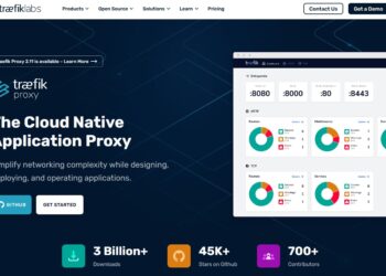
In today's fast-paced digital landscape, the adoption of microservices architecture has become increasingly prevalent. With the rise of containerization and...

Are you tired of trying to save Instagram profile pictures, only to end up with blurry or pixelated images? Look...

Suralink is the leading PBC request list management software that offers efficient and cloud-based solutions for audit and document workflows....

The CareLogic EHR Platform is transforming healthcare management, revolutionizing the way organizations handle patient records and deliver care. With its...

Managing files and data on your Apple devices has never been easier with iMazing. Designed specifically for iPhones, iPads, and...

Did you know that 70% of people feel lonely sometimes? It's surprising in a world where we're always connected. Many...
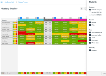
MasteryConnect is an innovative platform that is revolutionizing education by providing teachers with powerful tools to enhance student learning. With...

Looking for meaningful connections and your perfect match? Look no further than Dateyou, the premier platform that brings people together...
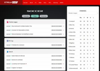
Welcome to StreamEast, the ultimate destination for sports enthusiasts who crave the thrill of live sporting events. StreamEast offers a...